
General Information
This plug-in let’s you create an Ambisonic decoder for any desired loudspeaker layout and Ambisonic orders up to 7th. The resulting decoder is automatically applied to the incoming Ambisonic audio stream, so it can be directly inserted into a decoder track of your audio project. You might also want to use it as a standalone application to design a decoder and write it into a JSON configuration file for the use in other plug-ins (e.g. SimpleDecoder).
A theoretical description of the AllRAD approach can be found here.
How to start
The first thing you want to do is inserting the loudspeaker coordinates (azimuth and elevation) and the channel numbers by clicking ‘add loudspeaker’. The fields ‘radius’ and ‘gain’ will only affect imaginary loudspeakers (see below). Loudspeaker at the same level as the listener’s head should by specified by an elevation angle of 0°.
You can click the Noise-button which will send a short noise-signal to the corresponding channel. That way you can verify whether your routing is correct.
The loudspeakers will appear both in the 3D visualization (top left) and in the loudness map (bottom left). The selected loudspeaker is visualized in green and imaginary ones in orange, while the others are blue. You can rotate the 3D view by dragging, and zoom in/out using the mouse wheel. As opposed to imaginary loudspeakers, physical loudspeaker directions are always visualized with a radius of one.
You can rotate the whole layout around the z-axis by clicking the rotate button. This will add a constant value to all azimuth angles.
After inserting enough loudspeakers, the layout is going to be triangulated immediately and it is also displayed in the 3D visualization. Any problems with your layout will be shown in the message area below the loudspeaker list.
Adding Imaginary Loudspeakers
Sometimes, a loudspeaker layout cannot be triangulated in a non-ambiguous way. With the AllRAD approach, imaginary loudspeakers can be added to circumvent these cases.
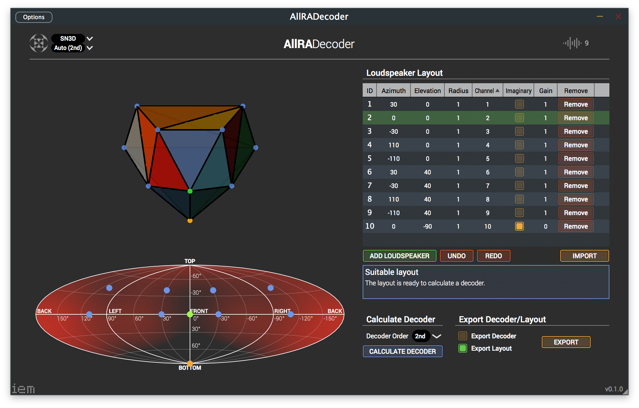
For example, almost every layout without loudspeakers in the lower hemisphere has an ambiguous ground plane. Inserting an imaginary loudspeaker just below the listener will prevent that case. The following layout depicts that example. You also might want to set the gain of that specific imaginary loudspeaker to zero, otherwise sources from below will be reproduced by all of the floor level loudspeakers. Download the configuration file for this layout here: layoutWithOneImaginaryLoudspeaker.json
However, in that layout there are several other planes, which could be divided into triangles in a different way: the top plane, left and right side, and also the plane right behind the listener. Additionally, there is no way the top plane can be triangulated symmetrically. It’s advisable to add imaginary loudspeakers here, too. In the following layout four additional imaginary loudspeakers were added. The configuration can be downloaded here: layoutWithAdditionalImaginaryLoudspeakers.json
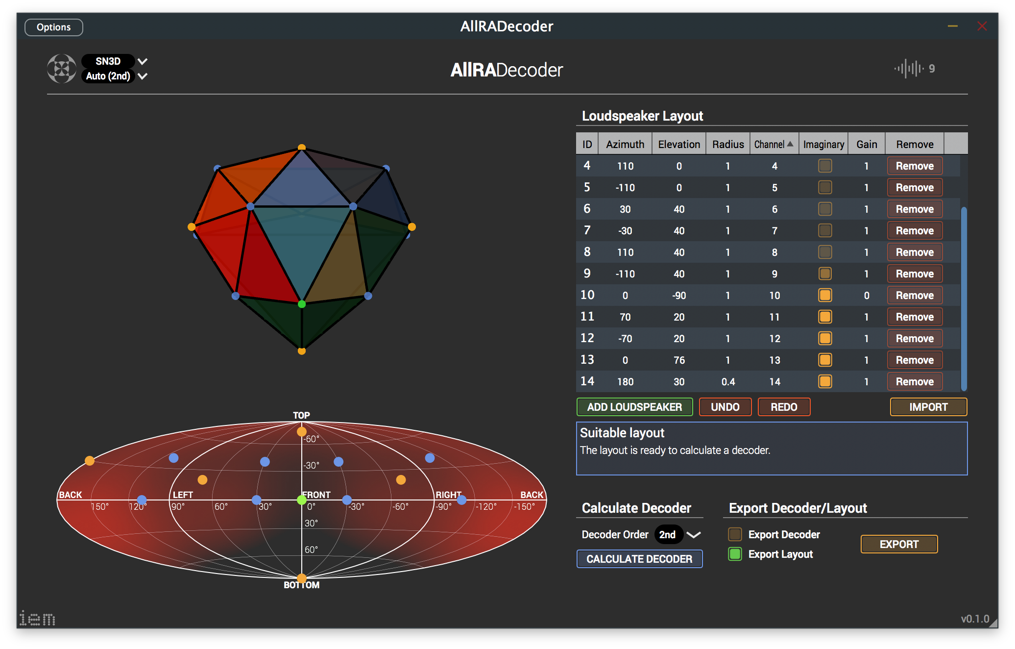
The gain is left unchanged, as one does not want silent spots in those areas. However, for loudspeaker #14 the radius had to be altered. Otherwise, there would have been a connection between two imaginary loudspeakers, which is not supported by the AllRAD approach.
Choosing a suitable Ambisonic order
The choice of the Ambisonic order is a trade-off between constant source width and smooth panning (low order) and precise localization and bumpier panning getting more similar to VBAP (high order). It’s typical to choose 2nd order for 60° spaced loudspeaker layouts, 3rd for 45°, and 5th order for 30°, respectively. 7th order is the highest you can choose and is suitable for 15° spaced layouts.
Energy distribution and rE source width map
When a decoder was calculated successfully, it’s energy distribution is shown in the loudness map in the bottom left (red). Peak values are visualized in red (up to +3dB) while areas of low energy (down to -3dB) are transparent. The choice of the Ambisonic order will influence the energy distribution.
When double-clicking on the map, it will display the acos-rE source width (green). The brighter the color, the wider the image of a source which is panned to that direction. In general, sources at a loudspeaker position will be smaller (less green) than sources between loudspeakers, as several loudspeaker will try to reproduce the signal.
Export Layouts and Decoders
You can export your layout to a JSON file by clicking the ’export’ button. Additionally, you can check the ‘Export Decoder’ checkbox to also write the calculated (don’t forget to calculate it first) decoder matrix to the configuration file, which e.g. can be used with the SimpleDecoder plug-in.
Future Features
In future implementations there will be more analysis than the loudness (energy) map, with maps of the rE-vector-based analysis of directional mapping and perceived width. Also the AllRAD2 approach will be implemented soon. It brings improvements to a panning-invariant loudness on typically irregular layout as the 4+5+0 layout from ITU BS.2051 with dense loudspeaker spacing only in front.